CNC
Toolchain A Notes
This toolchain is relatively simple, using Fusion for CAD and CAM and an Inventables X-Carve router for CNC. Everything listed is specifically aimed at woods (esp. hardwoods) unless otherwise noted.
Machine Specifications
According to an Inventables engineer I talked to, the specs of the machine are as follows:
| Work Area | 4' x 4' x 6" | |
|---|---|---|
| Spindle Dir. | Clockwise | |
| Spindle Speed | 16k to 24k RPM | It can go lower than 16k RPM, but it loses power stalls more easily. |
| Spindle Collet | ER16 | |
| General Tolerance | 0.002" | Small enough to simply ignore when engineering with wood. |
Coordinate Systems
The X-Carve works off of a righthanded coordinate system with the Z axis facing up off of the bed.
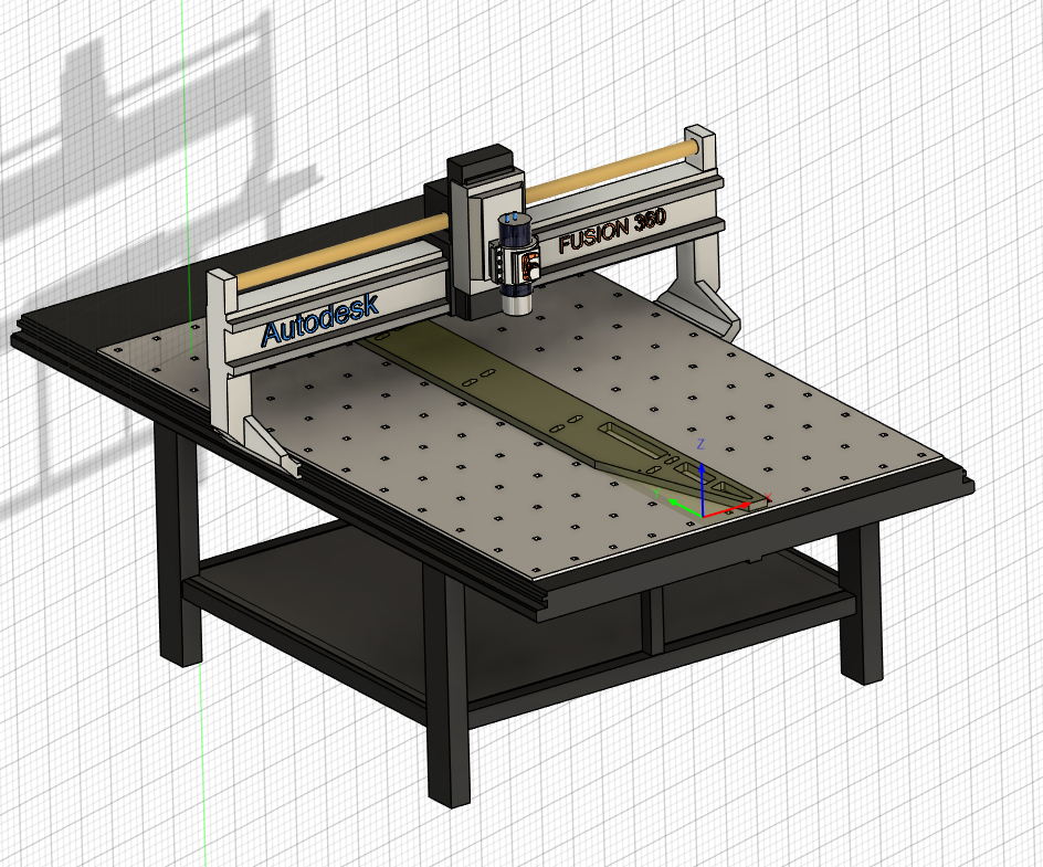
Note that for the X-Carve system, Z is generally zeroed to the top of the stock rather than to the bed. X and Y can, of course, simply be zeroed wherever as accuracy on those axes tends to be substantially less important. When choosing a machine in Fusion (not required but pretty), this is the YXZ generic router pattern.
Feeds and Speeds
Current best run values:
| Feed Rate | 150 in/min | |
|---|---|---|
| Plunge Rate | 45in/min | Can probably go higher |
| Ramp Rate | 45in/min | Can probably go higher |
| Depth Per Pass | 0.125 in | |
| Spindle | 16k RPM |
It's worth noting that Fusion will calculate the feed per tooth. This is a useful check to see if the rates are acceptable. Less than 0.001" is too low (for hardwoods), and will result in burning. Take care that the tool selected in Fusion has the same number of flutes as the real tool!
Freud End Mills
Freud publishes some "starting places". Note that even they are reticent to make deterministic statements - the document is half disclaimer! Below I have reproduced these tables. Here is a link to the docs for their good endmills.
| Tool Diameter | MDF / Particle Board | Laminated Particle Board | Hardwood | Softwood | Acrylics / Soft Plastic | Sold Surface / Hard Plastic | Plywood | Aluminum |
|---|---|---|---|---|---|---|---|---|
| 1/8" | .004"-.007" | 003"-006" | .002"-.005" | .004"-.006" | .003"-.005" | .002"-.004" | .003"-.005" | .003"-.004" |
| 1/4" | .013"-.017" | .010"-.015" | .008"-.011" | .010"-.012" | .006"-.009" | .005"-.008" | .006".009" | .005"-.007" |
| 3/8" | .018"-.021" | .014"-.018" | .014"-.016" | .016"-.019" | .010"-.012" | .008"-.010" | .015"-.018" | .006"-,.008" |
| 1/2" | .023"-.027" | .022"-.026" | .018"-.021" | .020"-.023" | .012"-.015" | .010"-.012" | .018"-.021" | .008"-.010" |
Solid Carbide
| Tool Diameter | MDF / Particle Board | Laminated Particle Board | Hardwood | Softwood | Acrylics / Soft Plastic | Sold Surface / Hard Plastic | Plywood | Aluminum |
|---|---|---|---|---|---|---|---|---|
| 1/8" | .002"-.004" | 003"-006" | .002"-.004" | .003"-.005" | 003"-006" | .002"-.004" | 003"-005" | N/A |
| 1/4" | .004"-.006" | .006"-.008" | .005"-.007" | .006"-.008" | .006"-.008" | .004"-.006" | .005"-.006" | N/A |
| 3/8" | .005"-.007" | .007"-.009" | .006-.008" | .008"-.010" | .007"-.009" | .005"-.007" | .006"-.008" | N/A |
| 1/2" | .006"-.007" | 008"-.010" | .008"-.010" | .008"-.012" | 008"-.010" | .006"-.007" | .007"-.009" | N/A |
| 5/8" | .006"-.007" | .009"-.011" | .008"-.012" | .009"-.013" | .009"-.011" | .006"-.007" | .008"-.010" | N/A |
| 3/4" | .007"-.009" | .010"-.012" | .009"-.013" | .010"-.012" | .010"-.012" | .007"-.009" | .009"-.011" | N/A |
Carbite Tipped Straight and Profile Bits
Toolpaths
Retract and Clearance Height
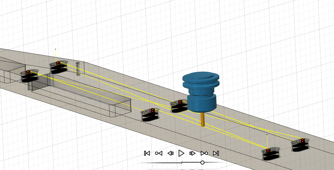
Retract height is how far the tool moves up in between moves within an operation. Clearance height is the height at which the tool starts and ends the operation. This can be a little tricky, as a multi-pocket operation will only hit clearance height at the very beginning and end. If there were clamps in between the pockets in the below image, they would be hit.
Thru-cuts and Stock Thickness
It's pretty hard to mill lumber down to +/- 0.001" accuracy. However, when milling a part with a thru-feature it's critical to have a very accurate knowledge of the stock thickness. I'm finding that it's much easier to simply measure the post-planed lumber thickness and adjust the model to match. This does mean that the GCODE must be re-generated just before the CNC operation, which can be annoying. It also has some concerning ramifications for any production work with milled lumber.
The bed of the X-Carve I'm using has seen quite a bit of action and isn't quite level. A margin is helpful to prevent cutting into the bed on thru-cuts. I have emperically determined this number to be certainly less than 0.03" and probably around 0.01".
Milling Small Holes
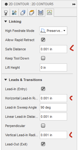
By default, Fusion refuses to mill out holes that are slightly (0.05") larger than the milling bit. This is due to some default values for toolpath lead in / out radius. Disabling Lead-In and Lead-Out or lowering the radius solves this.
Post Processing
Because the GCODE from Fusion gets imported into Inventables web-based control software (Easel) there are some extra steps. For starters, a post processor for Easel must be installed into Fusion. However, there's a little weirdness.
The movement to the first cut happens with G0X10Y20 (or whatever dimensions). This will happen at whatever height the machine is at when the program starts. If the tool starts just over the material (where the usual Easel pre-run zero routine leaves it) then it can dive straight into a clamp. It's useful to add a G0Z1.0 command just before the first G0 to ensure the tool starts high to avoid fixtures. It's also a very good idea to ensure that Fusion's retract height is set above fixtures as well.
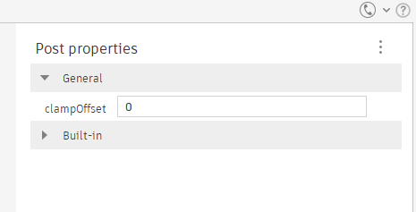
Note that the Easel post-processor has an option for 'clamp offset'. This is an X/Y offset, not a Z offset! Setting it WILL shift all work 'inwards' by a margin, which I found out the hard way.
There's also the risk of this happening at the end.
Custom Post Processor
I eventually found little tweaks I like to make to the start and end of the resulting GCODE file and almost immediately got tired of manually splicing that code in every time. So, I'm writing my own post-processor based on the Easel one.
- Autodesk Reference for CPS files
- Limited documentation for the functions within a post-processor.
- Post Processor Training Guide
- Long, in-depth overview of post-processor creation. Quite adorably provides a brief introduction to Javascript, in which post-processors are interpreted.
Practical Concerns
It seems that making sure all cuts are climb cuts really helps reduce tearout on edges when using a conventional spiral end mill.