Relay Motor Control
Simple and cheap
Synopsis
There are many way to drive even a simple DC motor. The cheapest and most straightforward method of doing so is with a relay. Naturally, a single relay can only drive a motor forwards at one single speed. However, many tasks only require this of a motor and more advanced solid state motor controllers would be overkill. In terms of dollar-per-amp of max control power the venerable electromagnetic relay can't be beat.
Components
There are millions of relays on the market. Below are a few of my favorites, with notes.
| P/N | Manufacturer | Max Voltage | Max Wattage | Datasheet | Notes |
| 2895 | Adafruit | 220DC 250AC | 60W | Relay | This is a breakout board that uses the EE2-3NUH relay. It costs about 3 times as much as the relay alone, but has an actual board profile with breakout etc. for convenience. Comes in latching and non-latching version. |
| 3191 | Adafruit | 250VAC, 125VDC | ~120W for inductive loads. | Relay | This is a breakout board that uses the Omron G5LE-14 relay. It costs about 5 times as much as the relay alone, but has an actual board profile with breakout etc. for convenience. See datasheet for load specifics (can double for non-inductive). |
Make v Buy
A similar breakout board to the above could be made, rather than bought, for about 50% of the price. Using a slice of a small protoboard like this, ($1.95) this relay ($2.62), and this small terminal block ($0.36) a similar small board could be made. Soldering the relay will be painful.
If the breakout board is purchased, usage is quite quick and simple. Furthermore, the Adafruit boards have built-in transistors to solve the GPIO-power-draw problem below.
Design
When using the Adafruit boards, it's sufficient simply to connect the Pi's 5v (specifically not the 3.3v rail - it hasn't enough power) and ground rails to the board's 3.3v and ground inputs. Then, a standard 3.3v line can be run from any of the Pi's GPIO ports to control the relay. "Design" is as simple as connecting some pins directly together.
The rest of this section is concerned with the use of relays directly. Control of a relay is simple, but the power required to trigger the relay can be somewhat high (between 30 and 100mA at 5v). Raspberry Pi GPIO pins, for example, often can't supply enough current to keep the relay closed. In those cases, a small transistor can be included to jump the 3.3V up to 5V and enough amperage.
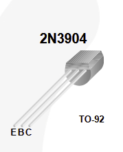
The venerable 2N3904 transistor is well suited to this challenge. The properties of this transistor by onsemi are listed below:
| Property | Value | Note |
| DC Gain | 100 | Varies with Ic from 30 to 100 |
| Max collector current (Ic) | 0.2A |
To provide 0.1A to the relay, at least 1/100th of that will need to pass through the base (0.001A). If the supply rail is 3.3V, that calls for a 3.3k Ohm resistor. A 50 Ohm between the 5v rail and the collector will provide 0.1A through the transistor to the relay. Note that, in practice, the load should be placed between the 5v rail and the transistor and its resistance will actually dictate these calculations.