CNC
Engraving with Inkscape and Fusion
Transferring an SVG from Inkscape into Fusion is straightforwards, but there are some tricks that save time and avoid some odd nuances of the two applications.
Contour Logistics
Strokes and Paths

When translating an SVG into GCODE that engraves it, everything comes down to contours. Closed contours are the actual fungible information that all software can understand.
However, when working with vector graphics it's easy to ignore or forget closed contours. For example, when drawing in realspace I love to cross-hatch. Naturally, when I draw in Inkscape it's familiar to use line work as a methodology (see example to the right). Lines are easy to work with - the thickness can be easily controlled, the points that compose it are straightforward to move, and end conditions are governed by basic rules.
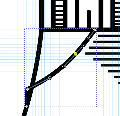
In the above image, you can see this is a simple line composed of points. However, when taken as a whole the line does form a contour. It's possible to use the line as a literal tool path, but that method is clunky and leaves a radius at all corners. It's far better to use the 'engraving' routine that Fusion provides, but engraving requires contours and this line does not form a contour on its own.
Fortunately, a line can be made into a closed contour with Inkscape's Stroke To Path feature. It took me an incredibly long time to realize this feature existed (the sort of search terms I came up with all featured the word 'offset', which proved to be a red herring). When used on a line, it produces a closed contour about that line which includes any miter or end geometry.
To get the best of both worlds, I follow this approximate method:
- Draw vector graphics with line work when and save the graphic instructionally as lines.
- Create a separate file for the 'export' SVG that will be sent to Fusion.
- Compose the export SVG with as many individual graphics as needed. Scale, rotate, etc. the line work and then all lines can be easily made the same thickness.
- At the last moment when all editing is done, convert lines over to contours with stroke to path.
- Import the resulting final product into a Fusion sketch.
This way it's very easy to go back and alter existing vector graphics.
Vector Graphic Purity
It is always easier to fix the vector graphic before getting to the sketch stage in Fusion. Fusion won't tolerate random debris or near-but-not-quite closed contours. Proper contour nesting is even more critical at the CAM stage. The very best time to fix a vector graphic is before leaving Inkscape.
The following is a short list of things to look out for:
Debris
Often I find artifacts and debris in imported vector images. Always check for this. Having the minimum number of 'clean' paths is imperative.
Near-Coincident Points
I've found that Fusion won't properly parse lines of their constituent points are too close together. It's a pain to zoom in and find these in Inkscape, but it's easy to merge them and certainly worth doing.
Fusion Feature Composition
Vector graphics can easily produce a horrendous number of individual contours. There's nothing worse than having to carefully select hundreds of small lines, contours, etc. in a CAD software, so below I've listed some tricks that speed things up.
1. SVG Imports are fraught with peril.
It's critical that the imported SVG actually divide up the surface into clickable contours. There are a number of quirks that can prevent this.
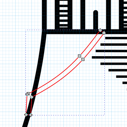
For starters, the sketch into which the SVG will be imported must actually be on the surface of the body which will be cut (see image below). It also should be the only sketch on that plane visible, as other sketches might take precedence for the UI and prevent proper contour selection.
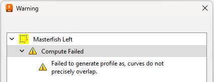
The error: "Failed to generate profile as, curves do not precisely overlap." will prevent contour collection. It seems to be more likely for larger / more complex imports. The following can help avoid this error:
- Ungrouping all sub-groups in Inkscape.
- Cleaning up the graphic in Inkscape before importing (see this section).
Always check that all of your contours have actually imported correctly. Fusion will just miss certain curve arcs sometimes. I'm trying to discern why this happens empirically...
2. Contour Selection
Once the contours have been correctly inserted into the sketch, selecting all of them can still prove a big pain. Some tricks I've discovered:
- Selecting from a non-normal view can expose contours for selection that would otherwise be unavailable for some reason.
- Selecting all contours in an area and then deselecting a handful can prove very fast.
3. Engraving "Depth"
Ultimately we want to do a simple extrude cut to create these contours in 3-space. The actual depth of this cut is (almost) completely irrelevant, as long as it doesn't cut through the material. The engraving CAM operation only cares about the 2D contour, not the 3D pocket. However, it can be handy to choose a depth of cut with an eye cast ahead to the re-selection of all these contours for the CAM step.
The engraving CAM operation can optionally select Same Face Plane's (see below). This is really, really handy if you have a great many different little contours that you don't want to have to individually click on. If you cut-extrude them all to the same depth, you can automatically select them all as a group.
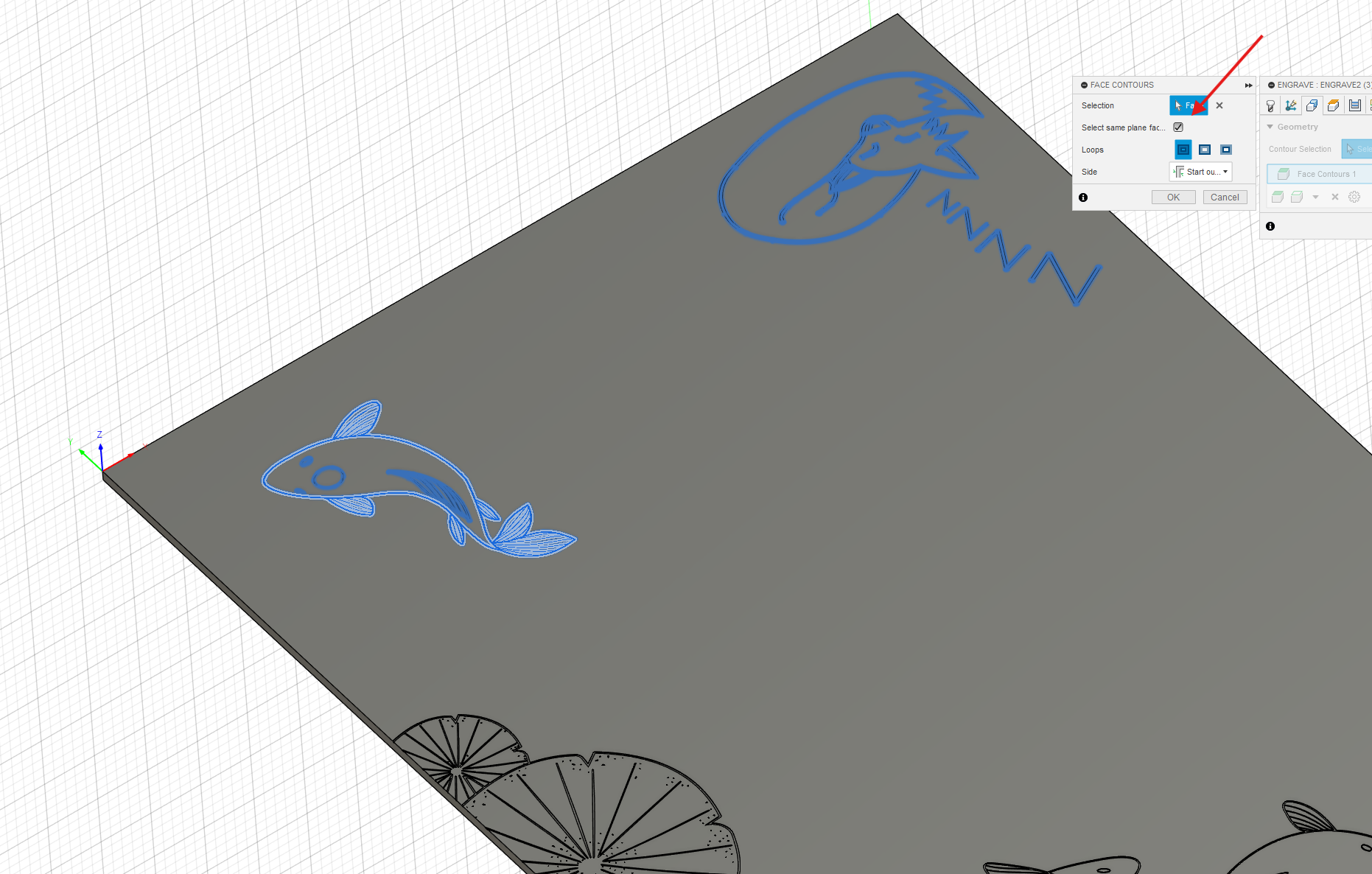
In the image above, I have a long piece of ply that can't all fit on the router at once. To CAM only each 'half' of the board, I put some of the cuts at 0.03" deep and the rest at 0.04". Only the ones at 0.03" are selected for CAM above.
Realspace Considerations
I have yet to deeply experiment with feeds and speeds, finishing passes, etc. The below will be rather unorganized notes on my findings when etching.
Findings
A Simple Finishing Pass on Baltic Birch
When cutting Baltic Birch, I've noticed these little fuzzy leftovers in the cut after a pass.